
 English
 中文简体

TBM crane
TBM crane
TBM crane
TBM crane
TBM crane
TBM crane
TBM crane
TBM crane
TBM crane
TBM crane
TBM crane
TBM crane
TBM crane

Industry News
 Nov 16 , 2026
The SAE Standard for Hoist Location Is: J-14302, JRP-2184 and Safe Lifting
Nov 16 , 2026
Content
- 1 The Short Answer: The SAE Standard for Hoist Location Is J-14302
- 2 Two Answers, One Principle: J-14302 and JRP-2184
- 3 What Hoist Location Really Means in a Service Bay
- 4 The Factors That Decide Hoist Location
- 5 From the Service Bay to the Factory Floor: Hoist Location Overhead
- 6 Design Choices That Change How Close the Hook Can Get
- 7 Setting Hoist Location Along a Runway: The Sequence
- 8 Myths and Realities About Hoist Location
- 8.1 Myth: any sturdy point under the vehicle will do
- 8.2 Reality: placement follows documented lift points
- 8.3 Myth: higher is safer because there is more room to work
- 8.4 Reality: height should match the task
- 8.5 Myth: standards only concern vehicle lifts
- 8.6 Reality: overhead lifting is heavily standardised
- 9 Standards Worth Knowing Around Hoist Location
- 10 How TBM Crane Thinks About Hoist Location
- 11 Frequently Asked Questions
- 11.1 The SAE standard for hoist location is what, exactly?
- 11.2 Why do two different designations exist for one question?
- 11.3 Does the SAE standard apply to factory overhead cranes?
- 11.4 How close can an overhead hoist hook get to the end of a runway?
- 11.5 What is low headroom, and why does it matter?
- 11.6 How should I plan hoist location for a new workshop?
If you have sat through an automotive service class, you have probably met this question in one form or another: "The SAE standard for hoist location is ______." It looks like a trivia item, and in most classrooms it is graded as one. But the blank is doing real work. It points at a simple, practical idea — the position of a hoist relative to the load it lifts is not a matter of convenience, but of engineering and safe practice.
That idea scales far beyond a service bay. The same question a technician answers about a two-post lift also sits behind every overhead crane decision on a factory floor: where does the hoist sit along the runway, how close can the hook travel to the end of the building, and how much headroom is left for the load?
This article answers the exam question directly, explains why two different designations keep showing up in study material, and then follows the principle from the workshop lift into industrial overhead lifting — the world where TBM Crane has been building hoists since 1984.
The Short Answer: The SAE Standard for Hoist Location Is J-14302
If you need one answer to fill in the blank, most current answer keys give J-14302. In the explanations that accompany those keys, J-14302 is described as the SAE document that sets out requirements for the safe and proper installation of hoists — in plain terms, where a hoist belongs and how it should be positioned so that it can do its job without putting anyone underneath it at risk.
It is not the only designation you will encounter. Flashcard decks built from automotive service textbooks record JRP-2184 for the very same question. Both answers circulate widely, which is exactly why the question feels confusing to anyone revising for a test.
What the question is testing
Not memorisation for its own sake. The examiner wants to know that you understand hoist placement is governed by a recognised standard rather than by personal judgement or by whichever bay happens to be free.
Where both answers come from
J-14302 appears in modern solution keys. JRP-2184 is reproduced in flashcard sets drawn from older classroom material. Textbook editions, quiz banks and answer keys are updated at different times.
Why the principle outranks the number
Whether the designation on your worksheet is J-14302 or JRP-2184, the message is identical: a hoist has a designated position, and that position is defined by documentation, not by habit.
How to settle it in your own workshop
Check the current SAE catalogue entry for the document, read the lift manufacturer's installation manual, and follow the vehicle maker's lift point information. Those three sources together answer the question for your bay.
Two Answers, One Principle: J-14302 and JRP-2184
When two numbers compete for the same blank, it usually means the underlying material has been paraphrased somewhere along the way. SAE publishes several categories of document, from full standards through to recommended practices and information reports. A recommended practice describes an accepted way of doing something; a standard carries firmer requirements. Quiz items taken from training books often blur that distinction, and the designation printed in the book becomes the "correct" answer for a generation of students.
The case for J-14302
Current answer keys and solution pages cite J-14302 and describe it as covering the safe and proper installation of hoists. That description matches the intent of the question: the examiner is asking where a hoist should be positioned, which is fundamentally an installation question.
If your course material is recent, this is very likely the answer your instructor expects, and it is the one supported by the explanations most students will find first when they search for help.
The case for JRP-2184
Flashcard decks built directly from automotive service textbooks list JRP-2184 as the SAE document for hoist location. The "RP" element is generally read as a recommended practice designation, and the number appears alongside other service-bay topics such as safety stands, asymmetric arms and stability checks.
If your quiz was written from an older edition of the same textbook, this is the answer keyed into it.
The practical takeaway is simple. Quote the principle confidently — hoist location is standardised because an incorrectly positioned hoist is a stability and injury risk — and treat the exact number as something to verify against SAE's own catalogue and the current edition of your course book. Designations are revised, and a document can be reaffirmed, superseded or withdrawn without the training material keeping pace.
What Hoist Location Really Means in a Service Bay
In the workshop, hoist location is not one decision but a short sequence of them, each made before the vehicle leaves the ground. The standard exists because each step has a failure mode attached to it.
1. Identify the supported points on the vehicle
Every vehicle has documented lift points. They are chosen by the manufacturer because the structure there is strong enough to carry the vehicle's weight without crushing a floor pan, a fuel line or a rocker panel. Location starts here, not at the hoist.
2. Match the hoist geometry to those points
Symmetric arms, asymmetrical arms and adapter extensions all change where the pads land. A hoist with asymmetrical arms sits the vehicle differently, and that changes the relationship between the pads and the recommended points.
3. Spot the pads with the vehicle low
Nobody can see a lift point from underneath a raised car. Positioning happens close to the ground, where alignment can be checked by eye and by hand.
4. Raise slightly and test for stability
A short lift, a firm push at each corner, and a second look at the pads. If the vehicle rocks or a pad has slipped off its point, the answer is to set it down and start again.
5. Raise to working height and engage the latch
A hoist can be stopped at any level as long as the safety latch engages. Lifting to the top of the travel for no reason only increases the height of a fall if something goes wrong.
6. Support anything you remove
Once a major component comes off, the vehicle's own structure is no longer carrying the load it was designed for. Tall safety stands exist for exactly that moment.
The Factors That Decide Hoist Location
The standard is a framework; the numbers in it come from the vehicle and the bay. Strip the question back to its engineering content and you are left with a short list of variables, all of which have to line up before a vehicle goes up.
| Factor | What it controls | Typical check |
|---|---|---|
| Documented lift points | Where the vehicle may be supported | Vehicle lift point information |
| Hoist arm geometry | Whether the pads reach those points | Symmetric or asymmetric arms, adapters |
| Weight distribution | Which end of the vehicle carries more load | Engine, transaxle and battery position |
| Hoist travel and latch | How high the vehicle may safely sit | Latch engagement at working height |
| Floor and anchoring | Whether the hoist stays put under load | Slab condition, anchor torque, level |
| Overhead clearance | Whether roofs, doors and antennas survive | Vehicle height plus working clearance |
| Safety stands | What holds a vehicle once a part is removed | Rating and height of the stands |
Read the table as a checklist rather than a procedure. In practice, the first two rows decide the rest: the lift points tell you where the load must be picked up, and the hoist geometry tells you whether your equipment can reach those points at all.
From the Service Bay to the Factory Floor: Hoist Location Overhead
Step out of the workshop and the same idea appears in a different form. An industrial overhead hoist is not a device that gets parked under a vehicle. It hangs from a trolley that runs along a bridge or a monorail, and its location is described in dimensions rather than in positions.
Three of those dimensions do most of the work. Hook approach describes how close the hook can travel to the end of the runway and to the side of the building. End approach is the distance between the hook centre, at its closest travel position, and the crane's end stop or buffer. Headroom is the vertical space the hoist and trolley consume above the hook, which is height that the load cannot use.
Together they define the working envelope. A hoist placed too far from a wall cannot serve a machine installed against it. A hoist with generous headroom in a building with a low roof cannot lift a tall workpiece off a truck. The location decision and the equipment choice are the same decision, viewed from two directions.
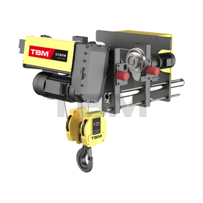 SHA8 Electric Wire Rope Hoist for Industrial LiftingA customizable 1–10 t hoist family with trolley and drum arrangements, useful when matching lifting capacity to headroom and hook approach.View Product →
This is where product design starts to matter. A wire rope hoist family such as the SHA8 series is built around a set of trolley and drum arrangements, so the same lifting capacity can be matched to different headroom and hook approach requirements. The question is never simply "how much can it lift" — it is "where can it lift, and how much room is left over when it does".
Design Choices That Change How Close the Hook Can Get
When a crane's working area falls short of what the process needs, the fix is almost always a change in hoist and trolley design rather than a new building. Three details matter more than the rest.
Headroom
Trolley and drum layout
In a low headroom arrangement, the rope drum is repositioned relative to the girder so that the hook can rise closer to the underside of the structure. The lifting height recovered at roof level becomes usable travel at floor level.
Reach
Hook approach dimensions
Side and end approach numbers decide whether a load can be set down in a corner of the bay or lifted over a machine that sits close to a column. They are specified, not estimated.
Travel
Trolley gauge and end carriage
A longer wheelbase spreads wheel loads more gently across the runway, but it costs end approach. The end carriage is the component where that trade-off is finally settled.
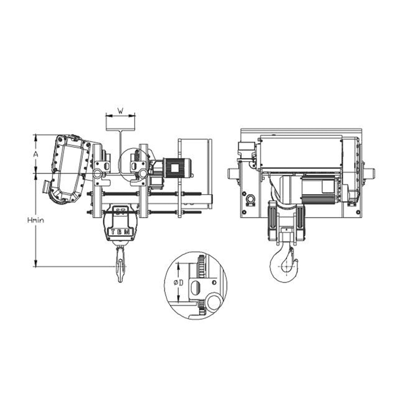 SHA8 Low-Headroom Electric Wire Rope HoistDesigned for workshops with restricted height, this hoist optimizes hook travel and crane structure while offering 1–12.5 t capacities and variable frequency control.View Product →
Low headroom designs exist precisely because buildings are expensive and roof heights are fixed. When a workshop cannot be rebuilt, the hoist has to be re-thought — and the result is measured in centimetres of recovered hook travel, which often decides whether a job can be done indoors at all.
Setting Hoist Location Along a Runway: The Sequence
On a real installation, hoist location is settled in a fixed order. Skipping a step usually means redoing the one before it, because the runway is the reference line that everything else is measured from.
Define the working area on paper
Mark the machines, aisles and storage positions the crane must serve. That footprint, not the available floor space, is what the crane has to reach.
Fix the runway line
The runway rail position sets the crane's travel axis and its span. Moving a rail later means moving structure, so it is decided early and then treated as fixed.
Place end stops and buffers
These components define the two extremes of travel. They are also what limits the end approach of the hook, so they belong in the layout drawing, not in the final week of installation.
Choose the hoist's extreme hook positions
Work out where the hook must reach in both directions and at both ends of the runway. The difference between that and the actual approach capability is the gap you have to close.
Verify headroom and clearances
Check the tallest load, the highest hook position and the structure above it. Nothing should have to be threaded through a gap that was never measured.
Confirm the power supply route
Festoon systems, conductor rails and control boxes all need space along the same runway. Their position constrains where the hoist can physically travel.
Commission the limits
Test the travel limits, the end stops and the load path under real conditions, then record the final dimensions for future maintenance.
 Crane Runway Rail for Stable Crane TravelProvides a stable, precise travel path and support structure; essential when layout and rail components determine whether a hoist can reach its intended work area.View Product →
Notice how many of these steps involve components rather than lifting capacity. Runway rail, end stops, conductor systems and control gear do not lift anything themselves, yet they decide whether the hoist can reach the place it was bought for. That is why an overhead lifting project is usually a layout project first and an equipment purchase second.
Myths and Realities About Hoist Location
A few assumptions survive in workshops long after the documentation has moved on. Here are three of the most persistent, set side by side with what actually holds.
Myth: any sturdy point under the vehicle will do
If the pad lands somewhere that looks solid, the lift will hold — so the argument goes. It usually does hold, until the day it does not.
Reality: placement follows documented lift points
Lift points are specified because the structure there is engineered for it. A pad on a floor pan can deform quietly during the lift and fail later, when the vehicle is already overhead.
Myth: higher is safer because there is more room to work
Raise it to the top of the travel and you have maximum clearance, minimum crouching, and a comfortable working position.
Reality: height should match the task
A hoist can be stopped at any level as long as the safety latch engages. Extra height adds fall distance and instability without adding useful access.
Myth: standards only concern vehicle lifts
Once you leave the automotive bay, positioning becomes a matter of layout preference rather than a documented requirement.
Reality: overhead lifting is heavily standardised
Industrial hoists, cranes and monorails are covered by their own body of standards and workplace regulations, and hook approach and headroom are specified within them.
Standards Worth Knowing Around Hoist Location
The SAE question is a doorway into a much larger set of documents. If your work touches lifting equipment at any level, these are the names that will keep appearing.
SAE J-14302
Cited in current answer keys as the document covering safe and proper installation of hoists, which is where location requirements sit.
SAE JRP-2184
The designation recorded in automotive service training material for the same hoist location question. Treat the number as edition-dependent.
ASME B30.16
Covers overhead hoists, including powered and hand chain types, and addresses installation and operating conditions.
ASME B30.17
Addresses top running bridge and gantry cranes, where span, end approach and runway geometry are defined.
ASME B30.11
Applies to monorails and underhung cranes, the arrangements most sensitive to where the hoist trolley sits.
OSHA 29 CFR 1910.179
The general industry rule for overhead and gantry cranes, covering inspection, testing and operating practice.
EN 14492-2 and EN 15011
European standards for power driven hoists and for bridge and gantry cranes, widely referenced in export markets.
None of these documents is a substitute for the other. A service bay lift, a workshop monorail and a double girder crane each answer to a different part of the family, and each defines location in its own vocabulary.
How TBM Crane Thinks About Hoist Location
Zhejiang Shuangniao Lifting Equipment has been building electric wire rope hoists and chain hoists since 1984, and the company's product line has grown around exactly the problem this article describes: matching a hoist to the space it has to work in. The SHA8 and SHA7 wire rope hoist families cover standard headroom, low headroom, single girder and double girder arrangements, while the SHH-A and ZH chain hoist ranges handle lighter capacities and specialised environments, including marine duty.
Around those core products sits everything that fixes a hoist's location: end carriages that carry the bridge along the runway, runway rail, conductor and festoon systems, control boxes, wheel blocks, inverters and wireless remote controls. For workstations that do not need a full bridge crane, aluminium light cranes, jib cranes, KBK systems, rigid light cranes and mobile gantries provide a smaller envelope with the same logic behind it.
The approach is deliberately unglamorous. Measure the building, define the work envelope, then choose the hoist that fits inside it. If you are planning a workshop and want a second opinion on where the hook should be able to reach, talk to our engineers about your layout. Our team also follows how lifting standards and workplace rules develop across the markets we serve, and we publish what is worth knowing in our industry news section.
Frequently Asked Questions
The SAE standard for hoist location is what, exactly?
Most current answer keys give J-14302, described as the SAE document covering the safe and proper installation of hoists. Some service textbooks and the flashcard sets made from them record JRP-2184 for the same question. If you are answering an exam item, use the designation printed in your own course material, and confirm it against the current SAE catalogue when accuracy really matters.
Why do two different designations exist for one question?
Because training material lags behind technical documents. SAE publishes standards, recommended practices and information reports, and quiz items often paraphrase them. When a document is revised or a textbook edition changes, the answer key in circulation can keep the older number for years.
Does the SAE standard apply to factory overhead cranes?
No. The SAE documents that answer this question are aimed at automotive service hoists. Industrial overhead hoists, bridge cranes and monorails are governed by other standards and regulations, including the ASME B30 series, OSHA 29 CFR 1910.179 in the United States, and EN 14492-2 and EN 15011 in Europe.
How close can an overhead hoist hook get to the end of a runway?
That is the end approach, and it depends on the hoist model, the trolley arrangement and the end carriage. It is specified for each configuration rather than assumed. When a process needs the hook to reach further into a corner, the answer is usually a different trolley or end carriage, not a longer runway.
What is low headroom, and why does it matter?
Headroom is the vertical space the hoist and trolley use above the hook. In a building with a fixed roof height, every centimetre consumed there is a centimetre the load cannot use. Low headroom designs reposition the drum and trolley so more of the building height becomes usable lifting travel.
How should I plan hoist location for a new workshop?
Work backwards from the process. Mark the machines and storage positions the crane must serve, establish the runway line, place end stops, then confirm that the chosen hoist's hook approach and headroom cover that footprint with clearance to spare. Only then compare lifting capacities.
The exam question about hoist location is a small thing, but it captures a principle that holds from a two-post lift in a service bay to a double girder crane spanning a fabrication shop. Position is designed, documented and checked — it is not improvised on the day. Get the location right and the equipment has a chance to prove itself. Get it wrong and no amount of lifting capacity will make up the difference.
News

The company has always attached great importance to new product development and technological innovation, focusing on a high starting point, high configuration
Product Categories
Contact Us

No. 9 Tenglong Road, Huangze Industrial Function Zone, Huangze Town, Shengzhou City, Zhejiang Province, China

info@tbmhoist.com

+86 - 18957539688
