
 English
 中文简体
中文简体
TBM crane
TBM crane
TBM crane
TBM crane
TBM crane
TBM crane
TBM crane
TBM crane
TBM crane
TBM crane
TBM crane
TBM crane
TBM crane

Industry News
 Sep 14 , 2026
Hoist Trolley Force Analysis: Three Forces Explained for Lifting Equipment Engineers
Sep 14 , 2026
Content
For a maintenance engineer checking a 5-ton overhead crane, the forces that hold the trolley in place on the bridge beam are not just academic numbers. A hoist trolley is subjected to the three forces in a typical statics exercise: the weight of the trolley itself, the load suspended from the hook, and the pull of the travel drive. The balance among these three forces decides whether the trolley stays aligned, whether the end carriage bears too much load, and whether the travel motor has enough torque to start and stop smoothly. Getting this balance right is the first step in choosing a reliable trolley system.
What the Three Forces Actually Represent in a Hoist Trolley
In a simplified plane-force model, the trolley is treated as a rigid body under three concurrent forces. The first is the weight of the trolley itself, including the hoist unit, the frame, and the travel machinery. The second is the vertical pull of the suspended load, transmitted through the wire rope or chain. The third is the horizontal driving or braking force applied by the travel mechanism to move the trolley along the crane bridge.
Each of these components has a real physical source on an overhead crane. The angle at which the driving force acts, often denoted as α in textbook problems, represents the direction of the applied force relative to the horizontal. In practice, this angle depends on how the pulling force is routed and how the trolley is connected to the bridge and end carriage.
- The trolley self-weight is usually the smallest of the three forces but still contributes to wheel loading.
- The suspended load is the dominant vertical force and drives the selection of the hoist capacity.
- The driving force must be sufficient to overcome rolling resistance, inertia, and possible brake forces.
The Standard Method for Solving the Three-Force Problem
Once the force directions and magnitudes are known, the solution follows the standard procedure for a coplanar concurrent force system. The setup usually begins by resolving each force into x and y components. If force P is applied at an angle α with the horizontal, force A acts horizontally, and force B acts vertically downward, the equilibrium equations are straightforward:
From the x-direction: P cos α + A = 0.
From the y-direction: P sin α − B = 0.
Solving these two equations gives P = B / sin α and A = − B cot α. The negative sign on A simply indicates that the horizontal force must oppose the horizontal component of P for the trolley to remain in equilibrium.
The table below shows how the required force P changes as the angle α changes, using a vertical load B of 400 lb as the input. The exact numbers are less important than the trend they illustrate: a smaller angle requires a larger driving force, and a larger angle changes the load distribution on the crane rail.
| α (degrees) | P = B / sin α | Practical note |
|---|---|---|
| 30 | 800 lb | High driving force; significant horizontal reaction on the rail. |
| 40 | 622 lb | Moderate force levels; representative of many industrial trolley layouts. |
| 50 | 522 lb | Lower P, but the vertical component of P increases the downward load on the track. |
| 60 | 462 lb | Smallest driving force; the pulling direction is more upright, which changes the wheel load path. |
The practical implication is that changing α by even 10 degrees can change the magnitude of the required driving force by nearly 20 percent. This is why the angle must be defined carefully from the start, not treated as an afterthought.
How the Analysis Guides Component Selection
Once the forces are resolved, the resulting loads become the design inputs for the trolley's mechanical parts. The vertical wheel load is the primary input for the crane end carriage selection. The horizontal driving force determines the required drive motor torque and the rating of the crane wheel block. The suspended load, plus dynamic effects, decides the hoist's rated capacity.
In a real crane system, the end carriage is manufactured with a defined wheel base and rail diameter to match the expected wheel loads. Selecting a standard end carriage without checking its connection to the trolley frame and its ability to bear the calculated wheel load is a common source of mechanical failure. When a trolley is subjected to the three forces described in the static analysis, the end carriage bears the largest share of the vertical reactions. This is why TBM's crane end carriage product line is designed with reinforced sections and robust wheel bearings to handle vertical and horizontal force combinations.
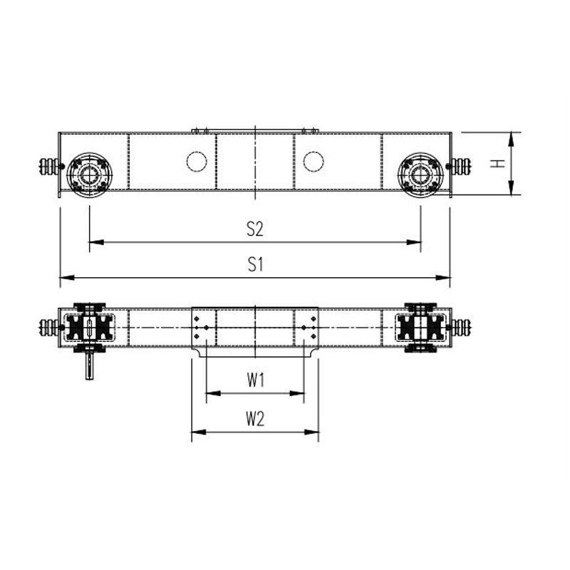 Crane End Carriage for Trolley Systems with Reinforced SectionsDesigned for heavy vertical and horizontal force combinations, this end carriage supports the crane bridge and travel mechanism, providing stability and durability for industrial applications.View Product →
Practical Considerations Beyond Static Equilibrium
Static equilibrium is the starting point, not the final answer. Working load limits, safety factors, and duty classifications all influence whether an equipment design is safe for daily operation. For a general-purpose electric wire rope hoist, the European FEM standard or an equivalent duty classification such as ISO M3 to M5 is often used to define how many hours per day the hoist can run at a given load. This duty factor is not arbitrary; it affects the size of the brake, the grade of the wire rope, and the thermal capacity of the motor.
The three-force problem also does not account for load swing, wind forces on an outdoor crane, or the effect of an inclined runway. These additional loads must be considered in the overall design of the trolley system. The wheel block must be evaluated for both static load and the horizontal forces that come from driving and braking. When the trolley accelerates or stops, the inertia of the load applies an additional horizontal force that is not part of the textbook static problem. This extra force must be absorbed by the wheel flanges and the track. TBM's crane wheel blocks are manufactured with flange-hardened wheels and sealed bearings to withstand repeated lateral loading.
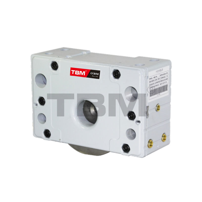 Durable Crane Wheel Block with Flange-Hardened WheelsBuilt with high-strength alloy steel and sealed bearings, this wheel block withstands lateral loading from acceleration and braking, ensuring smooth and precise crane travel.View Product →
Building a Safe Trolley System with TBM Lifting
From a component perspective, the three-force problem enters every stage of a trolley system. The end carriage must carry the wheel loads, the wheel blocks must handle the horizontal travel forces, and the wire rope hoist must be selected with the correct lifting capacity and speed. TBM Lifting builds the SHA7 standard-headroom electric wire rope hoist and SHA8 double-girder hoist with European-style configurations that provide clear capacity margins for industrial trolley applications. The electric wire rope hoist range is sized with the trolley load path and wheel reactions in mind, so the component connection points are designed from the start to support the calculated forces.
When you specify a trolley system, start with the actual force diagram of your installation. Determine the suspended load, the trolley mass, the rail layout, and the angle of pull of the driving mechanism. With those basic inputs, the static calculation gives a clear range of operating loads. Then match those loads to a hoist and a set of end carriage components that are built for the same duty and safety standards.
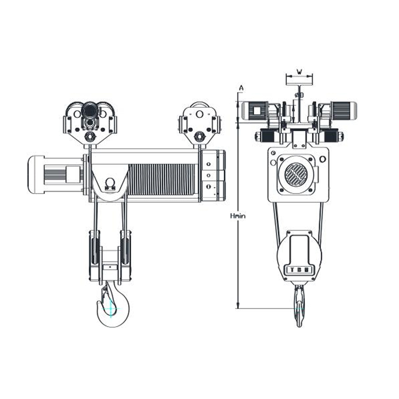 SHA7 Standard-Headroom Electric Wire Rope HoistEquipped with a high-efficiency motor and frequency conversion for smooth operation, this hoist is suitable for material handling in machinery manufacturing, automotive assembly, and other industries.View Product →
A hoist trolley is subjected to the three forces in this classic statics problem, but the real value of that calculation comes when it is applied to the design and selection of actual lifting equipment. The analytical method you use to resolve the loads is the same method that determines whether a trolley will run smoothly, stay aligned on its rail, and reach its designed service life. By matching the force solution to properly rated hoists, end carriages, and wheel blocks, you can avoid the costly failures that come from under-sized components. For a force calculation based on your specific trolley and crane layout, reach out to the TBM technical team.
News

The company has always attached great importance to new product development and technological innovation, focusing on a high starting point, high configuration
Product Categories
Contact Us

No. 9 Tenglong Road, Huangze Industrial Function Zone, Huangze Town, Shengzhou City, Zhejiang Province, China

info@tbmhoist.com

+86 - 18957539688
